Integrated Design Challenge
An autonomous and drivable robot using Arduino and Raspberry Pi
Context
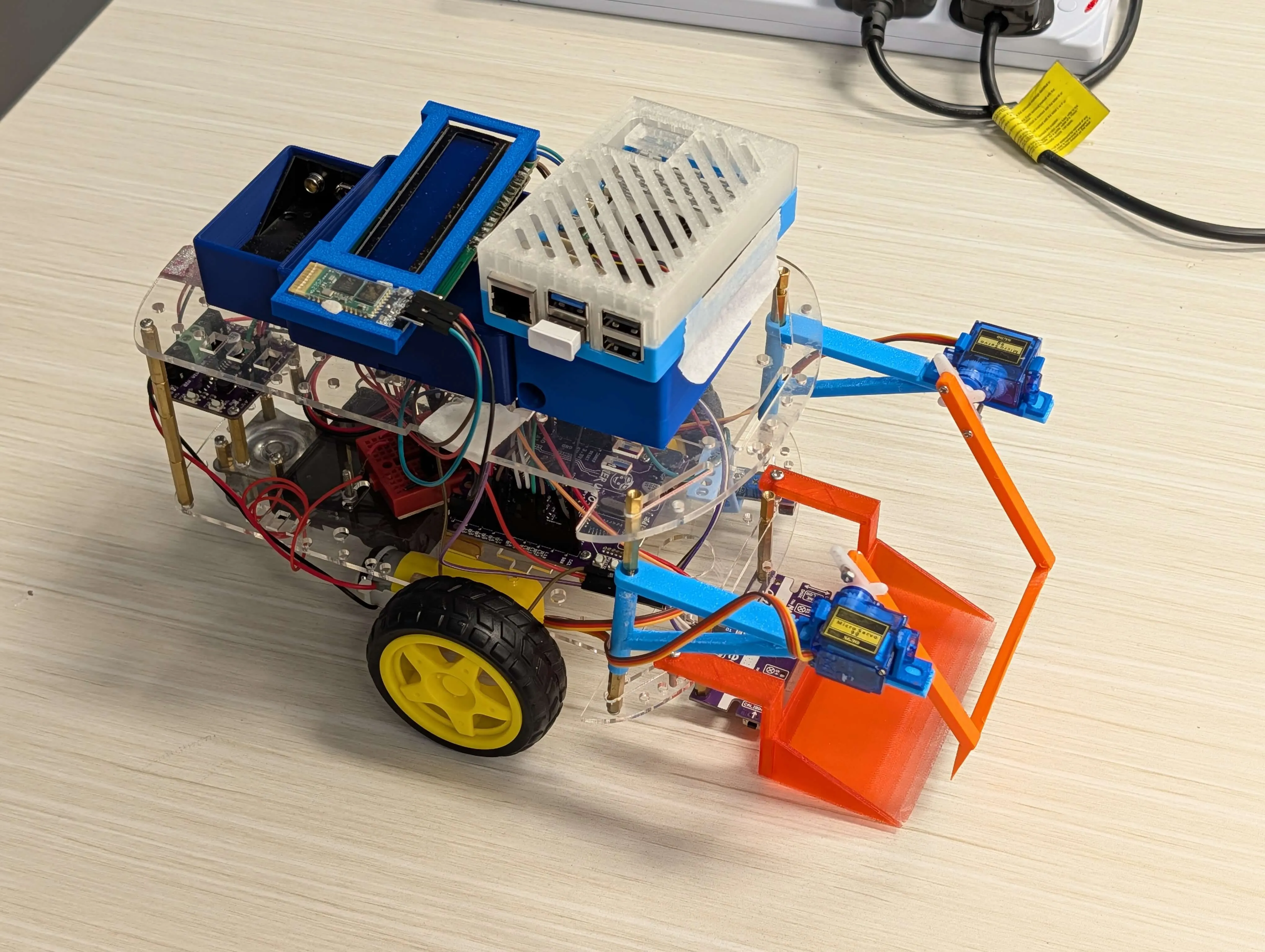
The Integrated Design Challenge was a cross-disciplinary project spanning 10 weeks where my team developed an autonomous and drivable robot using Arduino and Raspberry Pi that uses Computer Vision to identify objects and navigate toward them to achieve various objectives.
Autonomous Disaster-Response Robot
2026 Integrated Design Challenge
Overview
For the 2026 Integrated Design Challenge, my team built an autonomous disaster-response robot designed to navigate a playfield, identify hazard blocks using computer vision, pick them up with a custom gripper, and perform medkit inventory checks.
My main responsibility was integrating the computing and electronics systems. I worked on the overall control architecture, Arduino motor control, Raspberry Pi vision pipeline, and the communication layer between both boards.
One of the biggest design decisions was splitting the robot’s control system into two parts:
- The Raspberry Pi 5 handled the heavier vision tasks, such as hazard detection and medkit counting.
- The Arduino Uno handled real-time motor control, sensor reading, servo control, and state management.
This separation made the robot more reliable because the Arduino could continue handling time-sensitive hardware tasks, while the Raspberry Pi focused on higher-level decision-making.
System Architecture
The robot used a divided-control architecture, with the Raspberry Pi acting as the high-level processor and the Arduino acting as the real-time controller.
flowchart LR
  subgraph Edge Computing
      E["Raspberry Pi 5"]
      F["Pi Camera"] --> E
      E --> G["Hazard Detection Model"]
      E --> H["Medkit Counting CV"]
  end

  subgraph Real-Time Hardware
      B["Arduino State Machine"]
      A["5-IR Sensor Array"] --> B
      D["Bluetooth Manual Override"] --> B
      B --> I["Cytron Maker Drive"]
      B --> K["Dual SG90 Servo Gripper"]
  end

E <-->|"Custom UART/Serial Protocol"| B-
Arduino - Real-Time Control:
The Arduino ran the finite state machine for the robot. It handled PID line-following, junction detection, PWM motor control, servo movement, and Bluetooth manual override. -
Raspberry Pi - Vision and High-Level Logic:
The Raspberry Pi handled camera input, hazard detection, medkit counting, and target alignment. Instead of directly controlling the motors, it sent short command messages to the Arduino over serial.
This setup kept the system easier to debug and prevented the vision processing from interfering with low-level motor timing.
Custom Serial Protocol
One of the most important parts of the project was getting the Raspberry Pi and Arduino to communicate reliably.
Rather than sending large or complicated data packets, I designed a simple newline-terminated serial protocol. The Raspberry Pi would process camera data, calculate what the robot needed to do, then send compact commands to the Arduino.
For example, during target alignment, the Pi would send offset values showing how far the detected object was from the centre of the camera frame. The Arduino then used those values to make small movement corrections.
Target Alignment Sequence
sequenceDiagram
  participant A as Arduino (Actuation)
  participant P as Raspberry Pi (Vision)

  A->>P: STATE:ALIGN_TARGET
  note right of P: Pi captures frame and runs inference
  P->>A: ALIGN:-18:6
  note left of A: Robot makes a slight left correction

  A->>P: STATE:ALIGN_TARGET
  P->>A: ALIGN:4:7
  note left of A: Target is close to centre

  A->>P: STATE:TRACK_TARGET
  note right of P: Continuous tracking begins
  P->>A: TRACK:5:10
  note left of A: Robot moves forward in small pulses
The protocol also included a simple PING/PONG heartbeat. If the serial connection dropped or became unstable, the Arduino could detect it and enter a recovery state instead of continuing to drive blindly.
Challenges and Solutions
1. Moving from Timed Turns to Feedback-Based Control
In the first version, the robot used timed motor commands for turning. This worked during early testing, but it quickly became unreliable. As the battery voltage dropped, the motors produced less torque, so the same timed command would result in different turning angles.
Solution:
I replaced timed movements with feedback-based control using the camera alignment states. Instead of assuming the robot had turned far enough, the Raspberry Pi continuously checked the target position and sent updated offsets to the Arduino.
This made alignment much more consistent because the robot was reacting to what it could actually see, rather than relying on fixed timing values.
2. Handling Motor Deadband
The TT motors driven by the Cytron Maker Drive had a noticeable deadband at low PWM values. Speeds below around 50 often were not strong enough to move the robot, especially during small alignment corrections.
Solution:
I added a minimum effective speed check in the Arduino motor control code:
// Prevent motor stalling during micro-adjustments
if (speed > 0 && speed < MOTOR_MIN_EFFECTIVE_SPEED) {
    return MOTOR_MIN_EFFECTIVE_SPEED;
}
This ensured that even small correction commands from the vision system would still translate into actual movement.
3. PID Line Following
The robot used a 5-sensor IR array for line following. The sensor readings were converted into an error value, which was then passed into a PID controller for steering corrections.
After testing, I found that the robot needed fast reactions at junctions more than long-term accumulated correction. Because of that, I used a proportional-derivative setup with no integral term:
- Kp = 25.0
- Ki = 0.0
- Kd = 10.0
Keeping Ki at zero helped reduce overshoot, especially during sharper turns and junction pivots.
Key Takeaways
This project taught me how different real-world robotics can feel compared to writing software in a controlled environment. A lot of the hardest problems came from the interaction between code and hardware: battery voltage changes, motor deadband, mechanical delays, noisy sensors, and serial communication issues.
The most valuable part of the project was learning how to build a bridge between high-level software decisions and low-level physical control. The Raspberry Pi could decide what the robot should do, but the Arduino had to make those decisions happen reliably in the real world.
Working on this robot also strengthened my interest in Computer Engineering and embedded systems. I enjoyed working close to the hardware layer, and this project made me more interested in understanding how modern computing systems are built - from microcontrollers and bare-metal programming to AI accelerators and processor architecture.